
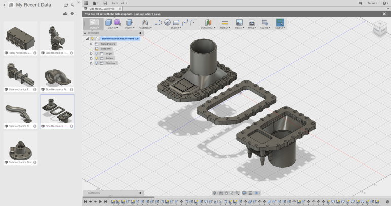
It’s been a while since I’ve updated the BatBerry blog. I’ve been heads down working hard to bring Brainiac to market. I’ve had a few people ask me to upload the remaining 3D models for the Side Mechanics. I haven’t had a chance to test print every piece yet so please provide any feedback if there are parts of the model that still require some adjustment. All of the 3D STL printable files can be downloaded from here.
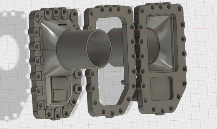
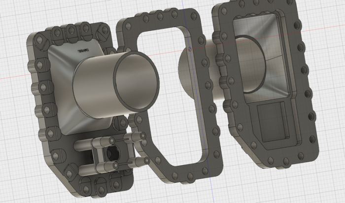
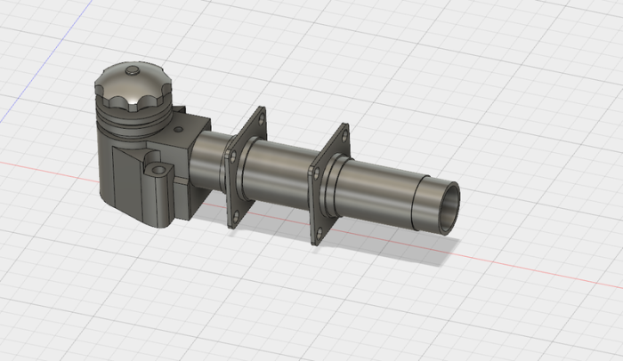
The 3D model files are broken up into different pieces that all fit together like a puzzle or, more accurately, like a set of PVC plumbing fixtures that can be glued together. First is the main Hot Air Valves themselves. They are broken up into three files: hot-air-front.stl, hot-air-middle.stl and hot-air-rear.stl. The same hot air valve is used on both sides of the vehicle. The valve simply points in the opposite direction on either side of the car so there is no need to flip the 3D model itself. The three pieces are held together with a series of bolts that go around the edges of the valve.
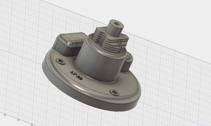
Next is the infamous “donut” which appears at the rear of the side mechanics next to the side intakes of the vehicle. This part consists of a round donut like body and a separate part that looks like some kind of cooling fins which are bolted to the top of the donut. They are broken up into two files: donut.stl and donut-fins.stl.
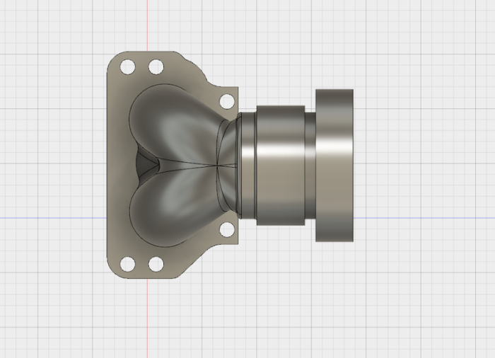
Starting from the front of the car there’s a heart shaped pipe that is bolted to the body and provides the front anchor point for the side mechanic piping. This same piece is used on both sides of the car so the same model can be used and simply 3D printed twice. You are then able to use a length of standard 1.5″ PVC plumbing piping to connect the heart to the “coffee can” which will be outlined later. The file to download for this piece is called: front-heart.stl.
Below this heart shaped piece is a fixture that looks like some kind of faucet. This is yet another part that is entirely for decoration. My guess is that they were looking for different pieces that would create a sense of balance for the pipes on the side of the car. This is one that simply fills up some space.
The part has been designed with some bolt holes for fastening it to the vehicle as well as some holes for the decorative bolts that run parallel with the body of the pipe. I created the end of the pipe with a diameter just under 1″ so that it would be fairly easy to find a fitting to connect/glue/thread hoses to the end of the faucet. This is another model that simply needs to be printed twice and used on both sides of the vehicle. There is one single print file for this part named: faucet.stl.
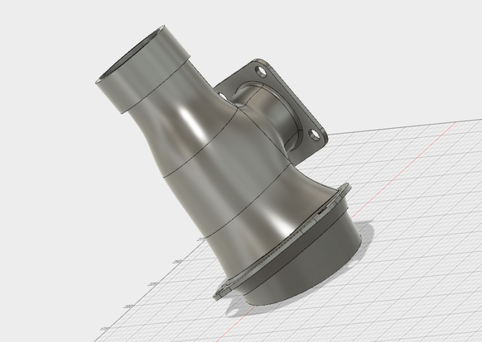
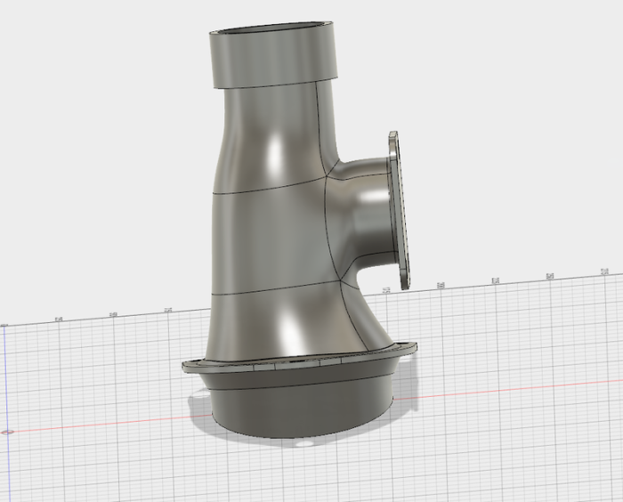
As we continue to move our way back down the side of the vehicle we come to the “coffee can”. This is another strangely shaped piece of piping that has three connection points. One using the 1.5″ PVC piping going down to the front heart, one connecting to the side of the vehicle and one that connects up to the Hot Air Valves. To print the coffee can there are two files. They are essentially identical, other than one is the mirror of the other to provide the proper angles on both sides of the car. The two files for this part are named: driver-coffee.stl and passenger-coffee.stl.
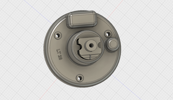
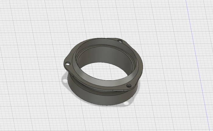
Heading towards the back of the vehicle the next part is the front ring. The coffee can slides into this front ring allowing you to glue the two pieces together. This ring is also the piece that joins the coffee can to the hot air valves. You may need to trim the front tube on the hot air valves for length depending on how close you want the coffee can to be to the valves.
This same ring is used on both sides and can simply be printed twice. To get the look of the V-band clamp from the actual side mechanics, I use a T-clamp that simply slides over this ring for decoration creating the same look without the added expense. The file to print for this section is named: front-ring.stl.
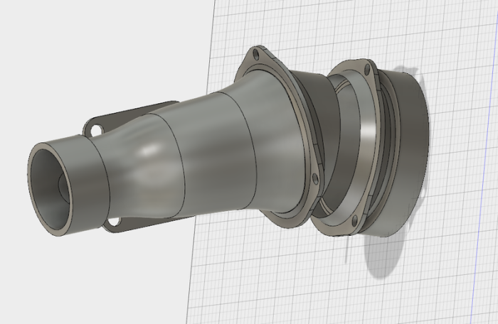
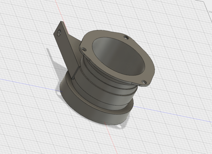
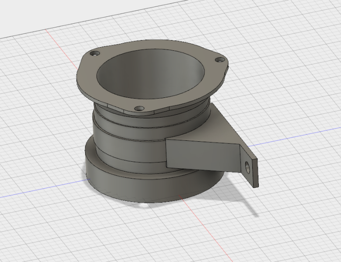
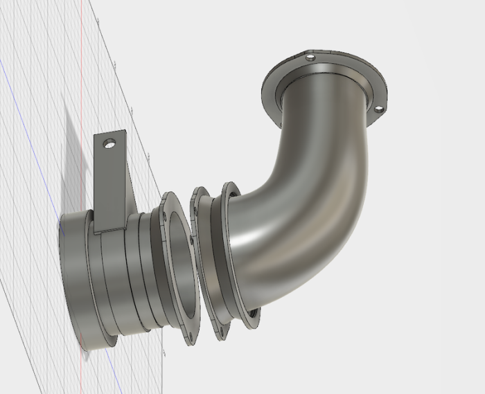
As mentioned above, the next part as you move towards the rear of the vehicle is the hot air valve which has been covered previously. After the hot air valves there is another rear ring that connects the hot air valves to the rear 90 degree pipe. These rings also have a support that reaches towards the side of the car to be used as another mounting point. Just like the coffee can, this rear ring has two files which have been mirrored to properly fit both sides of the vehicle. The two files to download and print for this part are: driver-rear-ring.stl and passenger-rear-ring.stl.
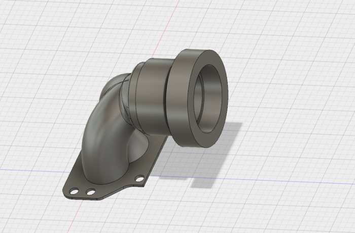
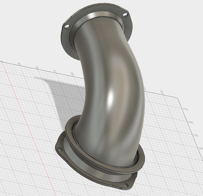
The finishing piece of the side mechanics connecting the hot air valves to the vehicle is the rear 90 degree pipe which is connected to the rear ring via their matching flanges. These two flanges are bolted together connecting the two pieces and finalize the piping. Just like the coffee can and the rear ring, this 90 degree pipe also requires two files that are a mirror of one another to create the proper angles on both the driver and passenger side of the vehicle. These two files are named: driver-rear-90.stl and passenger-rear-90.stl.
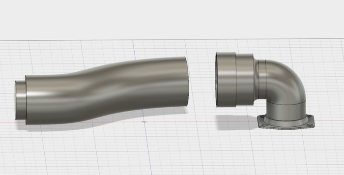
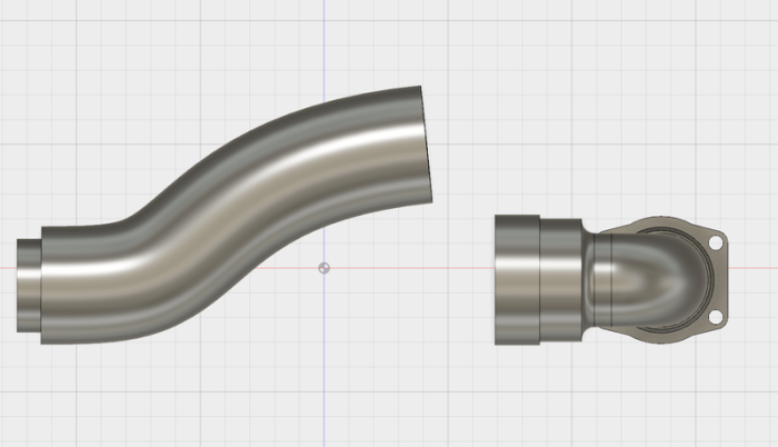
Below the rear of the side mechanics is a second lower curved pipe that connects back to the body using an angled fixture. Again I think this was simply placed here to create a sense of balance with the pipes. I’ve created the end fixture that connects to the vehicle as well as a curved piece of pipe. This curved pipe slides into the fixture and also has a stub on the opposite end that fits perfectly inside of standard 1.5″ PVC piping.
This allows you to use the same 3D model for both sides of the vehicle and also adjust the length of the pipe simply by trimming a piece of 1.5″ PVC. I really don’t know how this pipe is connected behind the hot air valves, but in the worst case scenario you should be able to print out another end fixture to connect it back to the vehicle body. The two 3D files to download for these parts are: lower-pipe-curved.stl and lower-pipe-end.stl.
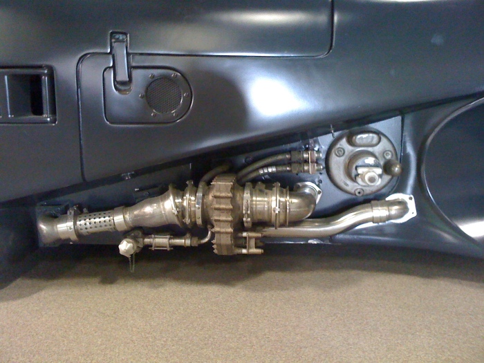
Hopefully all of these files will help those out there building Batmobile replicas achieve their goal of the “holy grail” of accurate looking side mechanics. For those of us who painstakingly struggle over the details, this is one of the areas that we look at first when checking out a replica. How close did the builder get to attaining the holy grail.
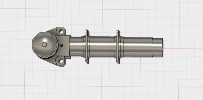
If everything comes together, and things are finished off nicely, the final result should look something like this… 🙂

Great work thanks Tim. Do all these bits join into each other…is that the idea?
Hi Craig, Yes they join into one another to create kind of a PVC piping like fit that can then be glued together. The rear 90 degree pipe is bolted to the rear section using the matching flanges.
Awesome work. I am getting quotes now to get them printed…so will let you know how I go.
Cheers
Thank you for sharing your work. Just goes to show there are still good people out there! Thanks Tim.
Thanks for the kind words Dan! 🙂
Tim – it is so generous of you to share these files so freely! I will get them downloaded and printed. Let me know if there is anything I can do to return the favor! Billy
It’s my pleasure Billy. Let me know if there is anything that needs to be adjusted 🙂
Tim – got all the files back from the printer today and they look REALLY good! Reading this post and looking at the pictures I can see how it’s all going to marry up and I know with a little sanding, prep, paint and added do-dads here and there it will be a super authentic look! Thank you again for your selfless generosity in sharing the files! Billy
My pleasure Billy 🙂
Billy what was the rough cost to get them printed? I was quoted close to $8000 from one place, and down to $800 at another. And did you get ABS or PLA? Thanks
Craig – I had them done in three separate batches and all total it was $1,200 – $1,500 for everything. Had it done in ABS based on the recommendation of the shop that did the work here in Orlando. I uploaded a few files to an on-line 3D print shop and was taken back by the quote and it easily would have been in that $8,000 range if not more for everything. The guy I found locally did my jobs in between others, I paid him cash and let him do it in his time so he worked with me on the price. $800 sounds really good if they are going to allow enough time to get the print resolution to a decent level. Hope this all helps! Billy
Thanks for sharing these files Tim, I hope you are doing well. Im getting them printed up for my 89, cant wait to ditch the old funky fiberglass ones !! Has anyone out there got these 3d printed ones painted up and mounted?
I know there are a couple of guys on Chicks Love The Car that have printed them out… not sure if anyone has them painted and installed yet though. I personally haven’t seen a set painted and installed yet, but I haven’t been checking the board as often anymore 🙂
I have mine printed out, painted and mounted. In the end I didn’t sand them down or try and finish them any better than they came off the printer. Everyone who has seen them thinks they have been done in metal, so they must look alright.
Send me an email at craig.blackburn AT usq . edu . au and I can show pics to anyone that is interested
Hi Tim! Do you happen to know the dimensions of the largest piece? I am looking into getting a 3D printer I just want to see how big the printer is going to have to be if I want to attempt printing them on my own using your files – Thank you for being so generous!
Hi Travis,
I believe the biggest piece is the 90 degree elbow which is 20cm x 13cm x 11cm
I stumbled upon this today and read through Tim’s work on the side mechanics. I have been working on my 89 for 10 years. Well mostly looking at it. I just finished building a full sheet metal and fab shop for my self to finish this crazy build.Going now full speed. I too now draw in cad, for printers and cnc’s etc. Hopefully he see his work on my bat soon Ill circle back and attached photos….Rn
Thank Tim and bravo on such a great project! Any new updates from anyone here who can suggest best print shops to get this printed in 2022 at great price? Ron and Craig, can you attach photos of yours parts as noted above? Thanks!
You might try and get a hold of Matt Munson (YouTube channel : https://www.youtube.com/channel/UCsXrY2yQz9k5euvFVZeV_MA) He printed out these files, molded them and has cast resin copies
I am using what you have to CNC cut on my plasma and CNC unless you metal print these parts they will warp in the sun. Just a heads up . If anyone wants a set just send me a email info@fxpropsllc.com I love this blog by the way it’s really helped me along . My side mechanics are all metal and aluminum